Desertcart purchases this item on your behalf and handles shipping, customs, and support to South Africa.
โก Power your projects smarter, smaller, and cooler!
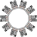
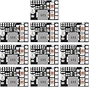
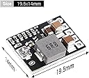
The DROK DC 12V to 5V Buck Converter is a mini voltage regulator board designed for professional-grade power management. Supporting input voltages from 4.5V to 20V, it offers adjustable output from 1V to 16V or fixed voltages including 5V and 12V, with a max current of 3A. Its ultra-compact size, high efficiency up to 97%, and integrated enable control make it ideal for precise, energy-efficient electronics projects. Sold in a convenient 10-pack, itโs perfect for engineers and makers who demand reliable, customizable power solutions.


| ASIN | B08Q3TKJH5 |
| Best Sellers Rank | #58,210 in Tools & Home Improvement ( See Top 100 in Tools & Home Improvement ) #229 in Power Converters |
| Brand | DROK |
| Color | Black |
| Customer Reviews | 4.4 out of 5 stars 39 Reviews |
| Input Voltage | 20 volts |
| Item Weight | 17.87 g |
| Manufacturer | DROK |
| Number of Items | 10 |
| Number of Outlets | 10 |
| Output Voltage | 5 volts |
| Power Source | Corded Electric |
| Unit Count | 10 Count |
D**T
WOW! Lowest Quiescent (Qi) Current of MANY!
Basic testing with output fixed at 3.3v and ENable control selected... Output is 3.34v. I didn't think it worked at first, but because I set the pad for ENable control, and that pin must remain set HIGH to maintain output on. MUCH easier than other bucks with EN control to use with a microcontroller! With circuit of 5v USB input and output of resistor-LED- and N-Channel MOSFET, it works fine. But with it keyed off by removing ENable pin power, the quiescent current is only 1.1uA!!!! So NO NEED for high side switching in battery powered project because current draw when keyed off is so amazingly slight!!! I think I just found my new best Buck friend. I like the pins all lined up with standard 2.54 spacing. Easy to breadboard or design into circuit board. Dropping 1.8v from 5v to 3.3v with slightest load of 4mA, there is no noticeable temp rise on the module. With same drop and 500mA load for 10 minutes, I still can't feel any temp change. If it came with a 4.2v fixed output option, I would totally declare this the PERFECT mini Buck! As of initial testing, I totally recommend this board without ANY reservations
A**L
Who doesn't need a good buck?
Easy to install. Mind your configuration paperwork. So... read the paperwork. If you are just slapping something together, stop and look for a dedicated supply. This product is configured BY YOU. Don't expect it be shipped with your configuration in mind.
C**S
A few things are missing from the description but otherwise a great product.
I've purchased about 20 of these now. They are realtly nice for controlling voltages higher than the microcontroller can tolerate. I use these to build small solar power displays with lights, fans, servos and motors. Using their enable pin, these buck converters allow a 3.3 micro to control and downregulate 12-14 volts of power to individual devices without having to separately add a switch, mosfet, or relay. The description of the device however suggests this is done through a pullup resistor. When I read this I thought I could simply overcome a (10k?) pullup resistor with the GPIO output from a micro sourced to ground and the device would shut off. This is not how they work. After a bit of playing, it's evident that there is a solder bridge near the enable pin that needs to be removed (cut or wicked away) before the enable pin can be used. If you simply apply ground to the enable pin it's a dead short and will quickly destroy the device and release the magic blue smoke. Once the solder bridge is cut, there is no pullup or pulldown resistor on the circuit. The voltage will float and act erratically. Once connected to the microcontroller it works perfectly though. This is a really nice feature at this price point and has saved me quite a bit of time wiring switches through other mechanisms. Removing the other solder bridge disconnects the potentiometer that adjusts the voltage just like the description says. The device will then require a new solder bridge on the back side to set the voltage. These pads are quite small and somewhat difficult to manage but it can be done. The potentiometers are a bit wonky and setting a perfect output voltage is a little tricky. From a power-saving standpoint, the device consumes virtually nothing when the enable pin is held low. My DMM reads 1.8 microamps--this is a huge plus over some other systems I have used. Running just an LED for testing purposes (4 mA), the device is 87% efficient. Using a 10 ohm resistor at 5.08v (500 mA) the voltage sags to 5.04 and the efficiency is 76%. Both of these were performed using an input voltage of 7v, efficiency is likely worse at higher voltages. Overall these work well for my purposes. The product description could have been clearer and had more of the details I included in this review.
C**R
Matches the Specifications
Used a bench supply, a couple portable meters, some resisters, and some nichrome wire for a load on the output side to test efficiency. Equipment used: fluke 87v, Innova 3320, ka3005p. Did a few cross checks and rearranged meters to improve accuracy confidence. The fluke was assumed to be the most accurate instrument of the lot. Focused on 12.6v to 3.35v. 3.35v was the measured output when the 3.3v pads were bridged. 12.6v "bucked" to 3.35v Salient findings: - Roughly 300 micro amps with no load on the output. - roughly 580 micro amps with 1 milliamp load - exceeded 90% efficiency at various points tested in the range of 200 milliamps to 2 amps. - 2 amp load yielded a drop from 3.35v to 3.29v (measured directly at output) - somewhere between 2 to 2.5 amps resulted in power cycling. Didn't look into the specifics of the ic used, but suspect thermal management would be needed for its full current range. - left output shorted for 5 mins and the device recovered once the short was removed The micro amp measurements are approximations because the Fluke's milliamp range was used to avoid excess burden voltage drop. Might not have been a concern but I didn't feel like getting that deep into it. These results let me know that the low power mode of my mcu shouldn't kill my auto battery if left for a couple weeks.
S**O
Excellent DIY 12VDC to variable 4.5-20VDC converter; Pot adjust for different LED colors!
This is an excellent DIY 12VDC to variable 4.5-20VDC converter with small .1 pitch (2.54mm) spaced holes for PC Board Standoffs. I found it difficult to modify for fixed DC voltages, but I do not have a precision conical tip for my soldering iron, micro Exacto blade and I do not have magnification loupes, that I believe are needed for the fixed voltage output modifications. If you do go ahead with the fixed VDC output mod and do not have the tools I mentioned, plan on sacrificing a couple of modules to get your accuracy down. As shipped from the factory, the variable DC Voltage Output seems to be 8VDC, and you'll need an approx 1/16" Precision Flat Head (slotted) Screwdriver to turn the potentiometer. Turn it approx 1/8 turn counterclockwise for 5VDC. The connection labels for + - DC Out and +- DC In and Control are on opposite sides from the potentiometer and the micro jumper you need to cut for fixed DC voltage out. The easiest way I found was to use without a PC board, but if you decide to use a PC board, you'll need to adjust the potentiometer or attempt to cut the micro jumper before soldering the module to the PC board. Great value for the money and Drok is a brand I absolutely trust for USB meters, which you should buy! https://smile.amazon.com/DROK-Voltage-Current-Display-Capacity/dp/B07FL5Y821 Update: Here's another reason to not used the fixed voltage mod. I'm using this lil guy w LED strings of the same color. Red LEDs require a smaller forward voltage drop @20mA (1.8VDC) than Orange (2VDC), Green (3.5VDC), Blue (3.6VDC0, White (4VDC). I use a 150 Ohm resistor and adjust the output voltage via the potentiometer so that the LEDs are not being over-driven (too bright). Great little board!
T**R
NOT the same as the 5 board order!
I needed 15 boards, so I ordered the 10 pack and a 5 pack. The 5 Pack are the ones I needed, the 10 pack are not. The 10 pack will do what they say they do, but unless you read the descriptions for each 'pack' you will get different boards - read and order by the description, not the quantity required.
R**O
Works perfectly for my use
I preferred to de-solider the variable adjuster and then solider the static 5v and 3v configurations. Not alot of effort and every one outta the 10 worked flawless. I'm ordering more.
F**F
Perfect for dioramas
Love the small size for powering dioramas and model kits.
Trustpilot
3 days ago
2 months ago